
| Resistance Unit Type | R-PSS-304 / R-PSS-406 (Fecrai) unbreakable Non Magnetic punched Stainless Steel GRID Resistor for 3.3/6.6 & 11KV system and Wire Wound Type for 440/550V system. |
| Service | Outdoor, humid, rainy and dusty environment |
| Rated Voltage | 11 KV – 6.6 KV – 3.3 KV – 550V – 440V |
| Rated Current | 50 Amps & 750 mA |
| Rated Duty | 10 – 30 Seconds stand. |
| Rated Resistor | For 11 KV - 127 Ohms, For 6.6 KV - 76.2 Ohms, For 3.3 KV - 38 Ohms, For 550 V - 425 Ohms, For 440V - 333 Ohms. |
| Power Frequency with Stand Voltage Test |
11KV / √ 3 - 6600 V : For 1 minute 6.6KV/ √ 3 - 3800V : For 1 minute 3.3KV/ √ 3 -2000V : For 1 minute |
| Temperature Rise | 350 degree C, rise over 45 degree C Ambient Temperature. |
| Degree of protection | IP 33 as per IS 2147 |
| Reference Standard | IEEE Standard 32 |
The enclosure of NGR shall be of Outdoor Version, Free Standing, Floor Mounting Type. The enclosure shall be made up of MS Structure duly pre-treated from anti corrosion covered with MS sheet removable type bolted & louvered side and rear covers and sloping top canopy. Fully enclosed cable termination chamber shall be provided at front of NGR for neutral & ground termination. The cable termination chamber shall be made up of 4 mm thick MS structure, front of cable box, shall have 4 mm thick MS bolted, removable cover. Rear of cable termination chamber shall be provided with relays and control terminals. Rear shall be double covered, inner cover shall mount the relays and transparent sheet shall be provided at outer cover for accessibility of the relays. The enclosure shall be suitable for outdoor installation with degree of protection IP-33. The Enclosure shall be Powder Coated painted.
There are power distribution networks those feed in certain earth-fault prone zone where the high earth fault current may lead to fire hazards and or damages to the cables or equipments. In those distribution networks the earth fault current is restricted within a stipulated limit. The neutral terminal (star point) of the power transformer is grounded through a suitable neutral grounding resistor (NGR) as a safety measure, so that the fire hazards and the damages to the equipment may not take place.
The above neutral grounding system alone cannot provide with a long time safety assurance. In out-door distribution stations there are many possibilities of damages to the neutral grounding connections due to various environmental effects. Those damages may cause open circuits in the grounding connection and or burning of NGR. That open circuit may result in failure of earth fault protection that operating through Neutral CT as the earth-fault current will not flow due to the open circuit of neutral grounding connection.
In respect of the above, it becomes necessary to install a device that will enclose a fall-safe operation of NGR and the grounding system. The device will continuously monitor the continuity of NGR and neutral grounding connections. And will trip the geeder circuit breaker as and when An open circuit takes place in the neutral grounding connections or in the neutral grounding resistor (N.G.R.). The device will ensure failsafe operation of neutral grounding system.
The NGR Monitoring and Protection Relay is a device that has been developed and made specifically for the failsafe operation of the restricted neutral grounding system. It has a highly insulated sensor. The sensor is connected to neutral-terminal of the transformer. The sensor has also the capacity to protect the relay from any sudden transient high voltage due to earth fault or any other reasons.
The relay ensures the failsafe function of the restricted neutral grounding system. It continuously monitors through its sensor, the continuity of NGR as well as the continuity of neutral grounding connections. It trips the circuit breaker as and when any open circuit takes place in the NGR, in the neutral grounding connections or also in the relay ground and sensor connections.
A separate Earth-Fault relay also provides earth fault protection to save the NGR. The relay senses earth fault current through a “Neutral CT”. When the fault current exceeds the limit, the relay operates to trip the circuit breaker. The relay independently protects the NGR from earth-fault.
Electrical power driven Equipments are used in various fields. The power to the mobile Equipments are fed from a field-switch through flexible trailing cables and couplers. The flexible trailing cable has three power cores, one earth core and one pilot core. For the purpose of safety the body of the mobile Equipments is grounded at the field-switch earth point through the earth core of the trailing cable. In case of any earth leakage/fault in the Equipment, the fault current flows from the Equipment body to the field-switch earth point through the earth core. The Equipment body remains at earth potential and the earth current operates the protection relays to trip the field-switch and interrupt the power supply. The discontinuity of the pilot core while disengaging cable couplers provides electrical interlock for tripping the field-switch. These arrangements provide safety to the people involved with the running of the Equipment.
The above arrangements alone do not provide long time safety assurance. There are possibilities of damage to the trailing cable or coupler during outdoor field operation of the equipment causing discontinuity of the earth core only without notice. In such cases the earth fault current as mentioned earlier, will not be able to flow through the earth core. The earth leakage/fault relays will not operate to trip the field-switch. The body of the equipment will be raised to phase potential and will dangerously remain live without any notice. This situation may lead to any accident and take human lives.
In respect of the above, it becomes necessary to install an additional monitoring and protection device that will provide a long term safety measure for the above earthing system. This/ additional monitoring and protection device will continuously monitor the continuity of the trailing cable earth core from the field-switch earth point to the equipment body. This monitoring and protection deice will sense any un-noticed discontinuation of the trailing cable earth core for whatsoever reason even for short circuit in the trailing cable or else and trip the field switch.
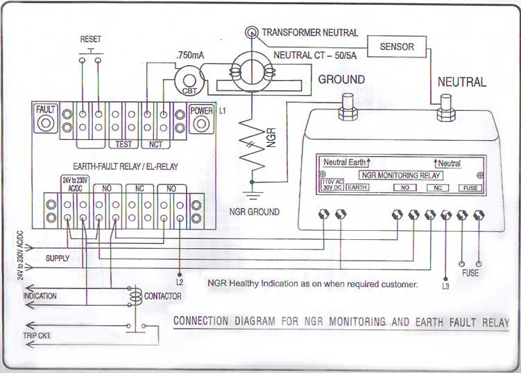
NGR Monitoring and Earth Fault Relay
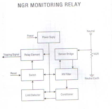
NGR Monitoring Relay
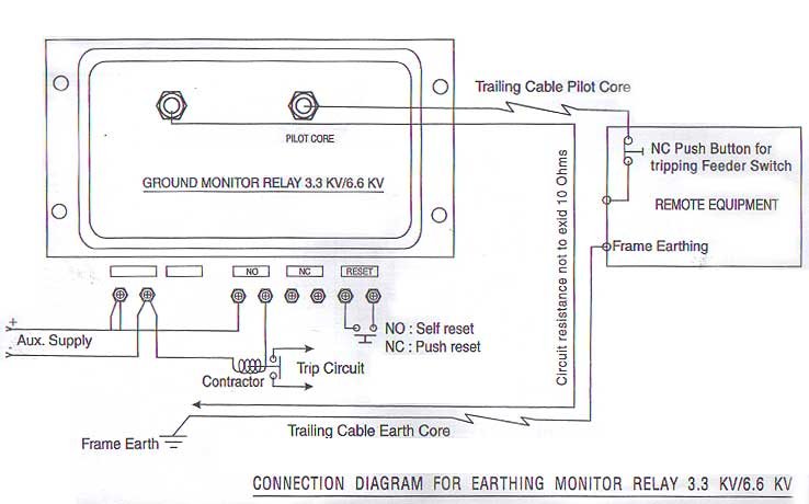
Earth Monitoring Relay
The earthing monitor and protection relay unit is a device that has been developed specifically to provide a long term safety measure for the earthing system used for electrical power driven mobile equipments. The relay unit that is mounted in the field-switch has a high insulated bridge sensor connected to the earthing terminal of the mobile through the pilot core of the trailing cable. The highly insulated bridge sensor protects the relay unit from any sudden transient high voltage due to earth fault or any other reason. The bridges sensor of the relay feeds a low voltage and current less than 5mA and continuously monitors the earthing circuit resistance to be higher than the set limit, the relay operates and send trip signal to the field-switch. Since the pilot core is also in the sensor circuit, any send trips signals to the field-switch. Since the pilot core is also in the sensor circuit, any discontinuation of the pilot core also trips the field-switch. The relay also provides safety interlock if the live cable couplers are disengaged by mistake. The relay continues to function even if the field-switch is off. The field-switch cannot be switched on unless the cable couplers are engaged properly.